

How to align the couplings of a motor rotor shaft?
Jan 06, 2026
As a trusted motor rotor shaft supplier, I understand the critical importance of coupling alignment in ensuring the smooth operation and longevity of motor systems. Proper alignment of couplings between a motor rotor shaft and its connected components is not just a technical necessity but a key factor in optimizing performance and reducing maintenance costs. In this blog, I will share comprehensive insights into how to effectively align the couplings of a motor rotor shaft.
Understanding the Basics of Coupling Alignment
Before delving into the alignment process, it's essential to understand what coupling alignment entails. Coupling alignment refers to the precise positioning of the motor rotor shaft and the driven equipment shaft so that their centerlines are in perfect or near - perfect alignment. Misalignment can occur in two primary ways: angular and parallel misalignment.

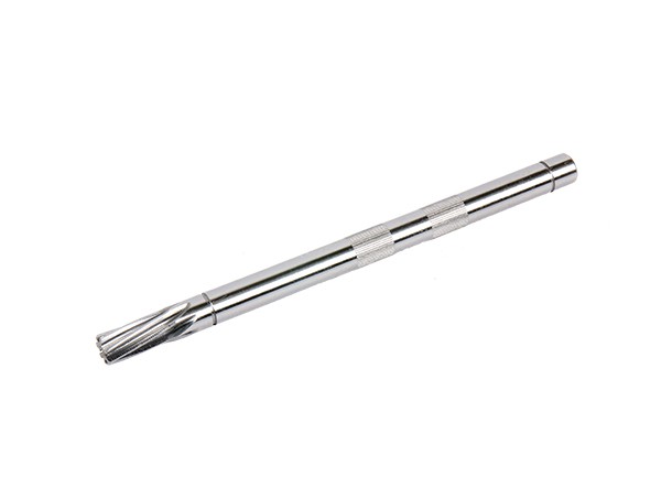
Angular misalignment happens when the centerlines of the two shafts intersect at an angle. Parallel misalignment, on the other hand, occurs when the centerlines of the shafts are parallel but offset from each other. Both types of misalignment can lead to increased vibration, premature wear of the coupling and bearings, and reduced efficiency of the motor system.
Tools Required for Coupling Alignment
To achieve accurate coupling alignment, several tools are commonly used. One of the most basic tools is a straight - edge. A straight - edge can be used for a rough initial check of parallel alignment. However, for more precise measurements, laser alignment tools are highly recommended. Laser alignment tools use laser beams to measure the relative position of the shafts and provide real - time data on misalignment, allowing for quick and accurate adjustments.
Another useful tool is a dial indicator. Dial indicators can be used to measure both angular and parallel misalignment. They are attached to the coupling or the shafts and can provide precise readings of any displacement or misalignment.
Step - by - Step Guide to Coupling Alignment
Step 1: Preparation
Before starting the alignment process, it's crucial to prepare the equipment and the work area. First, ensure that both the motor and the driven equipment are turned off and locked out to prevent accidental startup. Clean the coupling surfaces and the shafts to remove any dirt, debris, or rust that could affect the alignment.
Next, gather all the necessary tools and ensure they are in good working condition. Familiarize yourself with the equipment's technical specifications, including the recommended alignment tolerances for the specific coupling being used.
Step 2: Initial Visual Inspection
Conduct a visual inspection of the coupling and the shafts. Check for any obvious signs of damage, such as cracks or worn - out parts. Also, visually assess the general position of the shafts to get a rough idea of any potential misalignment. If a straight - edge is available, place it across the coupling faces to check for parallelism.
Step 3: Mounting the Alignment Tools
If using a laser alignment tool, follow the manufacturer's instructions to mount it properly on the shafts or the coupling. Make sure the tool is securely attached and that the laser beams are properly aligned with the target points on the opposite shaft.
If using dial indicators, mount them on the coupling or the shafts in a way that allows them to measure both angular and parallel misalignment. For example, one dial indicator can be used to measure the radial displacement (parallel misalignment), while another can be used to measure the axial displacement (angular misalignment).
Step 4: Taking Initial Measurements
Once the alignment tools are mounted, take the initial measurements of the misalignment. With a laser alignment tool, the device will display the current state of misalignment, including the amount of angular and parallel offset. If using dial indicators, record the readings at specific points around the coupling circumference, usually at 0°, 90°, 180°, and 270°.
Step 5: Calculating the Adjustments
Based on the measured misalignment values, calculate the necessary adjustments to be made to the motor or the driven equipment. For parallel misalignment, the adjustment usually involves moving the motor horizontally or vertically. For angular misalignment, the motor may need to be tilted slightly.
Many laser alignment tools have built - in calculation functions that can automatically determine the required adjustments. If using manual methods with dial indicators, specific formulas can be used to calculate the adjustments based on the measured values.
Step 6: Making the Adjustments
Once the adjustments are calculated, start making the necessary changes to the position of the motor or the driven equipment. This can be done by using shims under the motor feet to adjust the height (vertical alignment) or by using jack screws to move the motor horizontally.
Make small, incremental adjustments and re - measure the alignment after each adjustment. This iterative process ensures that the alignment is gradually improved until it meets the specified tolerances.
Step 7: Final Verification
After making the adjustments, take final measurements to verify that the alignment is within the acceptable tolerances. Check both the angular and parallel alignment values. If any deviations are still present, make further minor adjustments until the desired alignment is achieved.
Importance of Choosing the Right Shaft Components
In addition to proper coupling alignment, the quality of the shaft components also plays a significant role in the overall performance of the motor system. As a motor rotor shaft supplier, we offer a wide range of high - quality shaft products. For example, our Gear Shaft is designed to provide reliable power transmission and smooth operation. The Precision Step Shafts are manufactured with high precision to ensure accurate alignment and reduced vibration. Our Precision Shaft Sleeve offers excellent wear resistance and helps to protect the shafts from damage.
Conclusion
Proper coupling alignment of a motor rotor shaft is a crucial process that requires attention to detail and the use of appropriate tools and techniques. By following the steps outlined in this blog, you can ensure that your motor system operates at peak performance, with reduced vibration, lower maintenance costs, and longer equipment lifespan.
As a dedicated motor rotor shaft supplier, we are committed to providing high - quality products and technical support to help you achieve the best results in your motor systems. If you are interested in purchasing our motor rotor shafts or other related products, or if you have any questions about coupling alignment or other technical issues, please feel free to contact us. We look forward to the opportunity to discuss your specific needs and work together to find the best solutions for your applications.
References
- Machinery's Handbook, Industrial Press Inc.
- Alignment and Vibration Analysis in Rotating Equipment, Wiley - IEEE Press.